At first glance the UML specification can seem a little daunting. Java developers know all about classes, interfaces, and inheritance, but how do these concepts map to the UML? In Java terms, what are Elements, NamedElements, RedefinableElements, Classifiers, Features, etc.? This post aims to bridge the representational gap between some of the key UML Kernel package elements and the corresponding concepts that manifest themselves in a simple Java class.
The following code depicts a simple interface, abstract superclass, concrete subclass hierarchy in Java.
Operation.java
package math;

public interface Operation {
  double perform();
}
BinaryOperation.java
package math;

public abstract class BinaryOperation implements Operation {

  protected final double operand1;
  protected final double operand2;

  protected BinaryOperation(final double operand1, final double operand2) {
    this.operand1 = operand1;
    this.operand2 = operand2;
  }

  public abstract double perform();
}
Addition.java
package math;

public final class Addition extends BinaryOperation {

  public Addition(final double operand1, final double operand2) {
    super(operand1, operand2);
  }

  public double perform() {
    return operand1 + operand2;
  }
}
Class Diagram
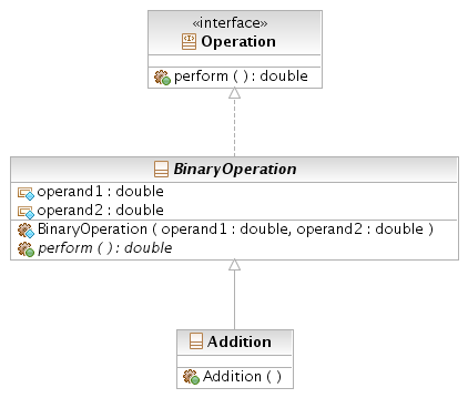
N.B. The remainder of this post assumes the elements are contained in model called "model".
Element
An element is a constituent of a model. The interface, classes, member variables, operations, parameters, etc. in the example code above are all elements. Elements can own other elements and have comments attached to them. The hierarchy of elements (listed outermost first) for the operand1 parameter of the BinaryOperation constructor is as follows:
- <package> model
- <package> math
- <class> BinaryOperation
- <operation> BinaryOperation
- <parameter> operand1
NamedElement (extends Element)
A named element has a simple name, a qualified name, and an optional visibility. The perform method in the Operation interface has following named element attributes:
- name = perform
- qualifiedName = model::math::Operation::perform
- visibility = public
PackageableElement (extends NamedElement)
The only difference between named elements and packageable elements is the requirement that packageable elements always have a visibility. For named elements the visibility attribute is optional. Classes and interfaces are both packageable elements.
Namespace (extends NamedElement)
A namespace is simply a container for named elements. In the code example, the following elements are also namespaces:
- <package> math
- <interface> Operation
- <class> BinaryOperation
- <class> Addition
- <operation> perform
- <operation> BinaryOperation
- <operation> Addition
This is all pretty straightforward. Packages contain named elements such as sub-packages, classes, and interfaces; classes contain named member variables and methods, and operations contain named parameters.
Package (extends PackageableElement, Namespace)
A package is essentially a namespace with the additional constraint that its directly owned elements must also be packageable elements. Because a package is itself a packageable element it can be nested within other packages. In the example the package math contains the packageable elements <interface> Operation, <class> BinaryOperation, and <class> Addition.
RedefinableElement (extends NamedElement)
A redefinable element is an element that has the capacity to be overridden. It adds a single boolean attribute, isLeaf. Setting isLeaf to true is equivalent to applying the final modifier, as is the case in the Addition class.
Type (extends PackageableElement)
A type constrains the values that may be represented by a typed element. In Java terms this equates to a primitive type, interface, or class.
TypedElement (extends NamedElement)
A typed element extends a named element by adding an optional association to a type. For example, the operand1 instance member variable in the BinaryOperation class is a typed element with an association to the type double<PrimitiveType>. The value it represents must be no less than java.lang.Double.MIN_VALUE and no greater than java.lang.Double.MAX_VALUE. Similarly, if we declared a variable of type Operation in some client object it would be constrained to referencing the set of Objects that directly or indirectly realise the Operation interface. (See StructuralFeature below).
Classifier (extends Namespace, RedefinableElement, Type)
A classifier is a namespace that can contain features (see Feature below). Classifiers also have the capacity to own generalisations, which in effect means they can extend other classifiers. In the example code, Addition owns a Generalisation relationship that targets BinaryOperation. Classifier adds a single boolean attribute, isAbstract. This is semantically equivalent to the abstract modifier in Java. The value for the BinaryOperation classifier is true.
Feature (extends RedefinableElement)
Features define the behavioural or structural characteristics of classifier instances. They can also be static, in which case they define a feature of the classifier itself. The following elements, owned by the BinaryOperation classifier, are all examples of non-static features:
- <property> operand1
- <property> operand2
- <operation> BinaryOperation
- <operation> perform
StructuralFeature (extends Feature, MultiplicityElement, TypedElement)
The structure of a classifier is defined by its structural features. In Java, a structural feature is an interface constant or a class member variable (static or non-static). StructuralFeature defines a single boolean attribute, isReadOnly. Supplying a value of true is equivalent to applying the final modifier to a Java member variable. In the case of the BinaryOperation classifier the following elements are structural features:
- <property> operand1
- <property> operand2
BehaviouralFeature (extends Feature, Namespace)
By defining a behavioural feature, a Classifier states that it will respond to a designated request by invoking a behaviour. A behavioural feature is also a Namespace in the sense that it may own zero or more named parameters. BehaviouralFeature defines an association to zero or more Types representing the exceptions that may be raised during its execution.
Interface (extends Classifier)
The UML concept of an interface and the Java concept of an interface are pretty much identical. As with Java, all the features of a UML interface must have public visibility.
Class (extends Classifier)
As in Java, a UML class defines a set of objects that share the same specification of features, constraints, and semantics. A class owns a set of attributes and a set of operations. These are represented by instances of Property and Operation respectively.
MultiplicityElement, Property, Operation, Parameter, and other elements
Like Interface and Class, many of these elements are self explanatory. The aim of this post has been to focus on the more abstract elements of the Kernel package, so I won’t list their details here. If you’d like further information, please consult the UML specification.
